How electricity is generated Reviews Exercises

5.10 How electricity is generated Reviews Exercises


1. Define the term “generator."
2. State the three major parts of a direct current generator.
3. With the aid of a sketch, explain how e.m.f. is induced in a direct current generator.
4. Explain how a simple direct current generator may be improved for greater e.m.f. induction.
5. Define the term ''piezoelectricity."
6. With the aid of sketches, explain how thermocouples may be used to produce a higher voltage.
7. Explain how solar cells produce electricity.
8. List three applications of solar cells in everyday life.
9. State two uses of geothermal energy.

How electricity is generated Key points

5.9 How electricity is generated Key points


1. A D.C. generator produces a unidirectional voltage and current.
2. The three major parts of a D.C. generator are stator, rotor and commutator.
3. The direction of the induced e.m.f. in straight conductor is determined by the Right-Hand Rule.
4. The direction of the induced e.m.f. in coil conductor or solenoid is determined by the Right-Hand Grip Rule.
5. Electrical energy may be generated by ways other than magnetism and chemical action.
6. A piece of electric crystal can generate electricity when subjected to a changing pressure across two of its sides (compressed or released).
7. A steady pressure applied to a piece of electric crystal will not generate electricity.
8. The most frequently used piezoelectric crystals are quartz, Rochelle salt and barium titanate.
9. Electricity is produced whenever there is a relative motion between two materials such as a glass rod and silk. This is called static electricity. We can simply say that electricity is produced by friction.
10. Radiant energy is another source of electricity:
a. a photovoltaic cell converts light energy into electricity,
b. all photovoltaic cells are composed of two layers of dissimilar semi-conductor materials.
11. When a light ray strikes the junction between the two layers of a photovoltaic cell, electrons are forced across it.
12. Modern solar cells are made of silicon and germanium semi-conductor material.
13. Geothermal energy is heat energy produced within the Earth.
14. Geothermal power is renewable and environmentally friendly.

What is geothermal power

5.8 What is geothermal power

Geothermal energy is heat energy produced within the Earth.

This form of energy is formed in two ways:
(a) When the earth was originally created (very small fraction of about 20 %)
(b) When radioactive elements disintegrate within the earth crust (about 80 %)

Even though the geothermal may occur deep within the earth crust, heat conduction can take place up to the earth’s surface or should there be liquids like water on the way, these may easily signify the earth’s internal heat existence in terms of geysers (hot springs) or vapours.   If the temperatures are high, as much 4000  0C, internal elements may melt and float on their parent solid elements.  Water on the other hand, is superheated to high as 370 0C.  .  The heat energy so produced is used heat water at the heat exchanger.  This has kinetic energy that is in turn directed to spin turbine.  The turbine converts kinetic energy to electrical energy.  A part from electrical energy supply, heat from geothermal can also be regulated for heating in homes.

Geothermal power is renewable and environmentally friendly.  The number of users has incredibly increased due to advancement in technology, however it suffers from limitation of its location and dear cost of construction of power plants.

It is believed theoretically, geothermal power if highly exploited, will eventually lower the impact the global warming.

The reliability of geothermal power has enabled this form of energy to be injected into the national grid to boost national power distribution.

Photovoltaics

5.7 Photovoltaics

A photovoltaic or solar cell consists of a rectangular or round piece of metal covered with a thin, transparent layer of oxide as shown in Fig. 5.7.1 The light rays striking the oxide layer penetrates this layer and then the junction between the oxide and the copper. The light rays force the electrons to flow across the junction, and so generating electricity.


When the light rays are interrupted, the e.m.f. generated by them disappears at the same instant. A photovoltaic cell made of copper and copper oxide is very inefficient. Modern solar cells are made of silicon which is a semi-conductor. These are more effective than those made of copper, Fig. 5.7.2.


Photovoltaics are used in a wide variety of modern electrical and electronic devices. A few applications are:
(a) Spacecraft power supplies.
(b) Light meters.
(c) Automatic-operated switches.
(d) Burglar alarms.
(e) Cellphone chargers.
(f) Home lighting.

Although photovoltaics depend on light for their operation, exposure to heat may damage them.

What is a thermocouple

5.6 What is a thermocouple

If the junction of two dissimilar metals is heated, the heat energy forces the free electrons of one metal into the other, thus generating an e.m.f., see fig 5.6.1.  This e.m.f. produced depends on two factors:
a) The type of metal used in forming the junction.
b) The temperature difference between the hot and the cold junctions.
A single pair of junctions (cold and hot) produces very little electrical energy.  The pair is what forms the thermocouple.

thermocouple_junction

To produce measurable electricity from thermocouples, individual thermocouples are sequentially arranged to form a thermopile.  During usage all the hot junctions are collectively placed close the area or substance whose temperature is being determined whereas the cold junctions are collectively placed within the fixed cold temperature.  This means that the cold junction is a reference or control temperature.  A simple hot and cold junctions’ circuit is shown in Fig. 5.6.2 for clarity.
Thermocouple_circuit


Typical applications of thermocouples are: flame detectors, furnace controls and heat detectors.

Static electricity

5.5 Static electricity

This is a mechanical method of producing electricity by friction.
When a plastic rod is rubbed with a cat's fur or a glass rod is rubbed with silk, electric charges are produced on the rods and on the materials they are rubbed with. While most of the mechanical energy used in the charging process is transformed into heat, a small amount is converted to electric energy.

electricity_by_friction
Electricity by friction


Electricity generated by friction is often undesired and from time to time can be dangerous to human beings and equipment. In printing shops, newspaper plants, static electricity is generated by friction and can give severe shocks unless special measures are made to conduct these charges to the ground. In nature, static electricity is produced when clouds move through the atmosphere and is known to cause a lot of damage to houses and trees by setting them on fire. Lightning is a form of static electricity and is known to have killed human beings and animals and damaged vegetation since time immemorial.

Piezoelectricity

5.4 Piezoelectricity

Electricity can be generated by exerting pressure on a crystal. A special kind of substance, the piezo electric crystal, converts mechanical energy into electric energy when pressure is exerted on it. Once a piezo electric crystal that is connected to a neon lamp is struck with a mallet, the neon lamp will emit a brief flash of light. A small portion of the mechanical energy is converted into electricity. Most of the energy is again transformed into heat. Fig. 5.4.1 illustrates the set-up.
Piezoelectricity_crystal


Piezo is a Greek word for pressure. Piezo electric crystals are made of such compounds as quartz, Rochelle salt, tour-maline and barium titanate. Usually the opposite sides of the crystal are silver plated and thin, flexible copper leads soldered to the plated area. When a steady pressure is applied, no electric energy is generated. The voltage produced by piezo electric crystal is very small and cannot be measured by a voltmeter. It requires to be amplified.

Piezo electric crystals are used in record players and microphones. The piezo electric crystal in the cartridge of the pickup arm is vibrated by the record groove. These vibrations produce varying degrees of pressure on the piezo electric crystal which in turn produces varying electrical signals. These are then amplified in order to operate the speaker. Piezo electric crystals are also used to deduce pressure changes in industries and production of spark in gas lighters e.g. cigarette lighter.

Lenz's law

5.3 Lenz's law

Lenz’s law deals with the direction of induced e.m.f. in a conductor.  To find out this, it good to know in which direction current will flow using a cell as show below.
direction_of_induced_emf_cell


A coil of known direction of wiring is shown below. In turn, if we plunge each pole of a magnet into and out of the coil; and we get the results shown figures 5.3.1b, 5.3.1c, 5.3.1d and 5.3.1e.

direction_of_induced_emf_in_a_coil_N_in


direction_of_induced_emf_in_a_coil_S_in

direction_of_induced_emf_in_a_coil_S_out

The above is generalized by Lenz’s law which states that the direction of the induced e.m.f. is such that it opposes the change causing it.  Approach by plugging N pole the end of the coil opposes it with the same pole and vice versa.
The direction of the flow in the coil can predicted by Right Hand Grip Rule.  This is done by gripping the coil with the thumb pointing N-pole and is perpendicular the fingers.  The fingers indicate the flow induced current.
On the other hand should it be a straight conductor be considered, fig. 5.3.1f, then employ the Right Hand (Dynamo) Rule which merely calls for taking the thumb, first finger and second finger being aligned to make right angles to each other as in fig. 5.3.1g and elaborated in fig. 5.3.1h.

Fleming's_right_hand_rule_cube


From the above laws, it will be evident that we need two basic components in order to generate an e.m.f. i.e.
a) a magnetic field,
b) a moving conductor.

A magnetic field can be produced in two ways:
a) By permanent bar magnets.
b) By electromagnets.
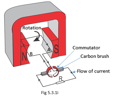
A more practical d.c. generator consists of a commutator connected to both ends of the conductor, as illustrated as a simple generator in Fig 5.3.1i. The purpose of a commutator is to change the direction of the current or voltage induced in the conductor. This always makes the meter to deflect in one direction and we can say the generator produces a d.c. induced e.m.f.
simple_dc_generator


When the conductor is horizontal or parallel to the flux, no e.m.f. is induced. When it is moved in a clockwise direction, the B side of the conductor moves upwards and the A side downwards. Using the Right-Hand Rule, it can be shown that the e.m.f. generated is in the same direction. When the conductors change positions, the split rings (commutators) also change positions and, therefore, the current in the external circuit does not change direction.
Hence the d.c. induced e.m.f. is only in one direction in the external circuit. This is how all d.c. generators function.
In a practical d.c. generator, there are many conductors forming many loops. Both ends of the conductors are soldered to the commutator segments. A commutator can be thought of as many slip rings mounted together, see Fig 5.3.1j.
The permanent bars of magnets are replaced by electromagnets in a practical generator. These improvements of the generator increase the d.c. e.m.f. induced.

practical_d.c._generator


A practical d.c. generator machine consists of three parts; namely:

A stator

This is the non-rotating part and can be made of permanent magnets or electromagnets.

A rotor

Is the rotating part of the machine and consists of loops of wire (insulated from each other) connected to the commutator segments.

A commutator

Is the part which converts the e.m.f. generated in a direct current and direct voltage (unidirectional). It consists of the commutator segments which are connected to the various loops of wire in the rotor. The brushes attached to the commutator send the generated e.m.f. to the external circuits.

Lenz’s law deals with the direction of induced e.m.f. in a conductor.  It states that the direction of the induced e.m.f. is such that it opposes the change causing it.
To determine the direction of the induced e.m.f. for conductor cutting magnetic flux, the following general rules apply:
for a straight conductor, use Right Hand (Dynamo) Rule (Fig 5.3.1g and Fig 5.3.1h), and
for a coil conductor use Right Hand grip Rule (Fig 5.3.1e)
Three major parts of a dc generator are stator, rotor and commutator.
Commutator can also be called split ring or current reverser.

Conditions for induced emf in a conductor

5.2 Conditions for induced e.m.f. in a conductor

This can only take place in the conductor when
1. there is relative motion between conductor (coil) and magnet (fig. 5.2.1b and fig 5.2.1c)
2. magnetic field lines are being cut by the conductor
3. cutting of the field lines must be perpendicularly to get maximum effect
4. the direction of e.m.f. depends on the direction of relative motion between conductor and direction of magnetic field lines (approach, fig. 5.2.1b and retreat, fig 5.2.1c)

Conditions_for_induced_e.m.f._in_a_conductor
Conditions for induced e.m.f. in a conductor


Summarizing, relative motion is needed between a magnet and a coil to produce induced e.m.f.s.  The induced e.m.f. increases when the relative velocity increases and when a soft iron core is used inside the coil.  The soft iron core concentrates magnetic field lines.


How electricity is generated

5 How electricity is generated

5.1 Direct Current Generator

A generator is a machine that converts mechanical energy into electrical energy. A direct current generator, thus, converts mechanical energy into electrical energy. It produces two electrical components:
(a) Direct voltage.
(b) Direct current.
A direct voltage is that which does not reverse direction. It can be represented by a continuous line above a certain point (reference point). This direct voltage is either positive or negative.

dc generator voltage vs reference point


A direct voltage can be steady if is constant with respect to time or it may be term unsteady if it fluctuates with respect to time as shown below:
dc voltage vs time
dc voltage vs time


All the above voltages are direct voltage because they are all positive with respect to y=0 axis when drawn from the origin.
Like the direct voltage, direct current is also represented similarly as shown below.
dc generator current vs reference point


Steady and unsteady current is represented below:
dc voltage vs time
dc voltage vs time

Cells and Batteries Review Exercises

4.7 Cells and Batteries Review Exercises

1. State the difference between primary and secondary cells.
2. Make a sketch of a zinc-acid cell and label its parts.
3. Explain how polarization and local action are prevented in the Leclanché cell.
4. Draw a diagram of a Leclanché dry cell and label the parts.
5. State two important features of the lithium air.
6. State the three factors which determine the e.m.f. of a cell.
7. Use schematic symbols to show how four dry cells are connected so as to provide double the voltage of one cell.
8. Explain the difference between cells and batteries.
9. State three reasons why lithium ion battery is preferred to power a smartphone than lead-acid battery.

Cells and Batteries Key Points

4.6 Cells and Batteries Key Points

1. An electric cell consists of two electrodes and an electrolyte.
2. Primary cells cannot be recharged, while secondary cells are rechargeable.
3. The zinc-acid cell is not commercially produced because it suffers from polarization and local action.
4. Polarization in cells is the process during which gas bubbles form on an electrode thereby insulating it from the chemical reactions of the cell.
5. Local action is the formation of local cells on the zinc electrode due to iron or lead impurities.
6. The Leclanché cell is the most commonly used wet or dry cell. It consists of a zinc cathode, a carbon anode, sal ammoniac electrolyte and a depolarizer.
7. The dry cell is manufactured in four sizes: D, C, AA and AAA.
8. The mercury cell is constructed small in size for powering small gadgets. It has a very high energy output for its size but due to its high mercury content it has been superseded by silver oxide, zinc air and lithium air cells.
9. Lithium air at the current has the highest shelf life and power output among the so called button or coin cells.
10. The e.m.f. of a cell depends on the materials of its electrodes and electrolyte.
11. Batteries consist of two or more cells connected together to supply large amounts of electric energy.
12. Cells are connected in series to achieve a higher effective voltage source.
13. Cells are connected in parallel to increase the effective current supply.

Secondary cells

4.5 Secondary cells

Secondary cells are rechargeable units. When they are depleted, they can be replenished by charging.

The most common secondary cells are:
1.       The lead-acid cells which make the car battery.
2.       The alkaline cells, such as nickel-cadmium cells.
3.       The lithium ion cell, which makes the cellphone battery and portable computer batteries are most recent.

Panasonic Lithium Ion Batteries


Because they are rechargeable, they are used as standby and emergency power supplies for hospitals, factories, schools, cellphones, tablets pcs and many others. They are also important for situations where higher currents are required, for example, in motor vehicles, aircrafts and mobile equipment used in remote areas.

Cells in parallel and series

4.2.3 Cells in parallel and series


Cells are connected in parallel and series to increase both the voltage and the current rating.  Below four cells are arranged in series to increase the effective to 6 volts and thereafter the series set are connected in parallel to increase effective current.  This increases current 3 times the single bank.

Cells in both series and parallel

Activity
  • How would modify the above arrangement and achieve 9.0 V?
  • Draw the schematic symbol of the resultant diagram.

Parallel circuit diagram

4.4.2 Parallel circuit diagram

Parallel circuit diagram of cells

If a higher current is required than that which a single cell can supply, a number of cells are connected in parallel.  When connecting cells in parallel, all the positive terminals are interconnected and all the negative terminals are connected to each other. This has the effect of adding the surface areas of the cell electrodes. The larger surface area can allow more chemical action and, therefore, more electric energy.

Connecting the cells in parallel increases the current rating, but the voltage remains the same if the cells are identical.  If however, the cells have different Emfs then effective Emf of the connection is equivalent to the highest value of the arrangement as show in the parallel arrangement below.

Parallel circuit diagram of cells2


Cells connected in series

4.4.1 Cells connected in series


This is done to increase the effective voltage output of the battery.  The battery output is the arithmetic sum of each individual cell.

Cells in series voltage
Cells connected in series

When four cells each of 1.5 volts are connected in series, the total voltage is (4 x 1.5 V) or 1.5 + 1.5 + 1.5 + 1.5 = 6V.

Circuit Diagram Symbols

4.4 Circuit Diagram Symbols


In a circuit diagram, the cells are represented by the symbols shown below. 
Electric cell symbol
Two cells in series symbol
Cells in series symbol
The long, thin stroke represents the positive electrode; while the short, thick stroke represents the negative electrode of the cell. These are conventional symbols and the polarity marks (+ or -) may be omitted.

Most electric cells source are 1.5 volts when new. This electric potential is too weak to deliver a large amount of electric energy. When this is needed, two or more cells are used. For example, a torch requires two size D cells to give enough light. But more powerful torches require three or four such units. Similarly, small radios require three size D cells, while the large ones require as many as twelve.

In principle, the term battery refers to more than one cell when used or connected together. Consequently, the two dry cells in a torch form a battery just as the six dry cells in the radio. The individual dry cell does not make a battery.


At times, manufacturers connect many cells and house them together to form powerful batteries. The 12-volt car battery consists of six lead-acid cells connected and housed in the same casing. In doing this the battery has enough power to start a car engine. Individual cells or batteries may be connected in various ways to achieve the required voltage and current supply.

Lithium air battery

4.2.7 Lithium air battery


Lithium air battery offers the best energy-to-size ratio compared to mercury, silver oxide and zinc air so far.  Similar in physical appearance as the named cells.

Button cell

Merits
It has a very long shelf life of up to 5 years to reduce capacity to 90% before being de-energized,
It has high e.m.f. of about 3.8 volts

Uses
Backup batteries for low-power computer memories, commonly known as CMOS battery
Portable devices where they are soldered into their circuits to last several years.

Nb. This battery should not be confused with the lithium ion battery used in cell phones which are secondary battery.  This is covered in KCSE Electricity Form 3 course work under storage batteries.

Voltage and Current Capacity of Cells

4.3 Voltage and Current Capacity of Cells

The e.m.f. of a cell depends on the materials of its electrodes and the electrolyte. On the other hand, the amount of current an electric cell can produce in a given span of time depends on the quality of electrodes and the electrolyte it is made of.

The table below shows the e.m.f. of some electric cells and the materials they are made of. 

Cell
e.m.f.
Positive Electrode
Negative Electrode
Electrolyte
1
Simple cell (Zinc-acid)
1.5
Copper
Zinc
Dilute sulphuric acid
2
Leclanché
1.5
Carbon
Zinc
Sal ammoniac
3
Mercury
1.35
Steel
Zinc
Potassium hydroxide
4
Silver oxide
1.5
Silver oxide
 Zinc
  potassium or sodium hydroxide
5
Zinc air
1.4
Oxygen gas
 Zinc
 potassium hydroxide
6
Lithium air
3.8
Oxygen gas
 Lithium
 Organic carbonate
7
Lead-acid
2.2
Lead dioxide
Lead
Dilute sulphuric acid
8
Nickel-cadmium
1.25
Cadmium
Nickel hydroxide
Potassium hydroxide
9
Lithium ion
3.6
Lithium cobalt oxide
carbon
Lithium salt in organic solvent

Zinc-air cell

4.2.6 Zinc-air cell


Looks similar to mercury cell but have about twice the capacity. It uses air in its chemical sequences, and are usually supplied sealed; pulling a tab off energizes the cell by letting air in. 

Zinc-air cell
Zinc-air cell


Merits
It has a very long storage or shelf life before being de-energized,
It has a high e.m.f. of about 1.4 volts, and
It is relatively cheap.

Silver oxide cell

4.2.5 Silver oxide cell


Similar in appearance to mercury cell, silver oxide cell provides a very stable and slightly higher e.m.f., 1.5 volts as compared to 1.35 volts of the mercury cell. Silver oxide cell’s cathode is made of silver oxide, with potassium or sodium hydroxide, both strong alkalis, as the electrolyte. The capacity of the silver oxide cell, size for size, is considerably better than that of the mercury cell. 
Silver oxide cell
Silver oxide cell

Because silver is expensive, this cell’s application is thus limited for applications where size and stability of voltage is of supreme importance, such as in watches and hearing aids.

Mercury Cell

4.2.4 Mercury Cell

This cell is also m common use and consists of:
an outer steel Container as the positive electrode,
a cylinder of compressed zinc powder in the centre of the cell as the negative electrode
potassium hydroxide as the electrolyte surrounding the zinc plate, and
manganese dioxide and carbon as the depolarizing mixture.

The cell is constructed so small that it is commonly used in watches, hearing aids, and miniature calculators. Its voltage is 1.35 V.
mercury cell
Mercury cell

The most important features of the mercury cell are:
It can be stored for long periods without losing its charge through local action.
It has a very high energy output for its size
Its drawbacks are:
It is toxic due to high mercury content
It is expensive
This cell has been replaced with a safer silver oxide cell.