5.3 Lenz's law
Lenz’s law deals with the direction of induced e.m.f. in a conductor. To find out this, it good to know in which direction current will flow using a cell as show below.A coil of known direction of wiring is shown below. In turn, if we plunge each pole of a magnet into and out of the coil; and we get the results shown figures 5.3.1b, 5.3.1c, 5.3.1d and 5.3.1e.
The above is generalized by Lenz’s law which states that the direction of the induced e.m.f. is such that it opposes the change causing it. Approach by plugging N pole the end of the coil opposes it with the same pole and vice versa.
The direction of the flow in the coil can predicted by Right Hand Grip Rule. This is done by gripping the coil with the thumb pointing N-pole and is perpendicular the fingers. The fingers indicate the flow induced current.
On the other hand should it be a straight conductor be considered, fig. 5.3.1f, then employ the Right Hand (Dynamo) Rule which merely calls for taking the thumb, first finger and second finger being aligned to make right angles to each other as in fig. 5.3.1g and elaborated in fig. 5.3.1h.
From the above laws, it will be evident that we need two basic components in order to generate an e.m.f. i.e.
a) a magnetic field,
b) a moving conductor.
A magnetic field can be produced in two ways:
a) By permanent bar magnets.
b) By electromagnets.
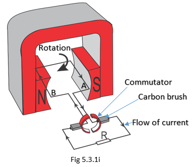
A more practical d.c. generator consists of a commutator connected to both ends of the conductor, as illustrated as a simple generator in Fig 5.3.1i. The purpose of a commutator is to change the direction of the current or voltage induced in the conductor. This always makes the meter to deflect in one direction and we can say the generator produces a d.c. induced e.m.f.
When the conductor is horizontal or parallel to the flux, no e.m.f. is induced. When it is moved in a clockwise direction, the B side of the conductor moves upwards and the A side downwards. Using the Right-Hand Rule, it can be shown that the e.m.f. generated is in the same direction. When the conductors change positions, the split rings (commutators) also change positions and, therefore, the current in the external circuit does not change direction.
Hence the d.c. induced e.m.f. is only in one direction in the external circuit. This is how all d.c. generators function.
In a practical d.c. generator, there are many conductors forming many loops. Both ends of the conductors are soldered to the commutator segments. A commutator can be thought of as many slip rings mounted together, see Fig 5.3.1j.
The permanent bars of magnets are replaced by electromagnets in a practical generator. These improvements of the generator increase the d.c. e.m.f. induced.
A practical d.c. generator machine consists of three parts; namely:
A stator
This is the non-rotating part and can be made of permanent magnets or electromagnets.A rotor
Is the rotating part of the machine and consists of loops of wire (insulated from each other) connected to the commutator segments.A commutator
Is the part which converts the e.m.f. generated in a direct current and direct voltage (unidirectional). It consists of the commutator segments which are connected to the various loops of wire in the rotor. The brushes attached to the commutator send the generated e.m.f. to the external circuits.Lenz’s law deals with the direction of induced e.m.f. in a conductor. It states that the direction of the induced e.m.f. is such that it opposes the change causing it.
To determine the direction of the induced e.m.f. for conductor cutting magnetic flux, the following general rules apply:
• for a straight conductor, use Right Hand (Dynamo) Rule (Fig 5.3.1g and Fig 5.3.1h), and
• for a coil conductor use Right Hand grip Rule (Fig 5.3.1e)
Three major parts of a dc generator are stator, rotor and commutator.
Commutator can also be called split ring or current reverser.


Thanks, my friend. It's a nice post. It's really appreciable. But if you provide some examples of Lenz's law. Then it will be a better post.
ReplyDelete